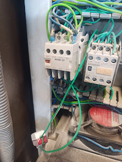
In electrical system, there are different types of loads and they need to be control or switch as requirement. For medium and large types of motor, they need to be controlled by using contactor and NO, NC switches. Here we will discuss about the contractor || Contactor main components, operating principle.
What is the Contactor?
A contactor is an automatic switching device that operates on the action of an electromagnet for repeatedly breaking and making of electric circuit. Also it can be used as a relay to switching power (generally for high power rating). Unlike relays, contactors have features of controlling and suppressing the arc produced when interrupting moving core of the contactor. Relays tend to operate at lower capacity and are usually designed for both normally closed and normally open applications. Contactors are designed in such way that can be directly connected to high-current load devices.
Contactor main components/parts
A contactor has three main components i.e contact, spring and electromagnet. The contacts are the current carrying part of the contactor which includes power contacts, auxiliary contacts, and contact springs. The electromagnet(coil) provides the force to close the contacts when supply provided to the contactor. The enclosure is, made of insulating materials like Bakelite, Nylon 6, and thermosetting plastics , a frame housing the contact and the electromagnet. Enclosures are made of insulating material to protect and insulate the contacts. Also it provides protection against personnel touching the contacts. For Open frame contactors, there is also features to protect against dust, oil, explosion hazards and weather. The devices that switches more than 15 amperes or a few kilowatts are usually called contactors. It is used to handle very heavy loads like an electric motor, heating equipment etc which draw more current but don't interrupt in case short circuit operation as a circuit breaker, MCB etc.
Operating principle of Contactor
When supply current is passing through the electromagnet i.e. contactor coil, a magnetic field is produced, which attract the moving core of the contactor to close the circuit i.e. supply to the load through the contactor. At initial, The electromagnet coil draws more current until its inductance increases when the metal core enters the coil. The moving contact, is propelled by the moving core in which the force is developed by the electromagnet in coil, holds the moving and fixed contacts together. When the contactor coil is de-energized, gravity or a spring returns to its initial position and opens the contacts i.e. circuit breaks.
Some points to remember in Contactor :-
1. NO :- In a contactor, there is written NO word on front which is also called NO switch, which means normally open. These points are used for control purpose. Always keep in mind that NO switch on contactor is used for holding the position of contactor i.e. if it is on, hold the contactor ON until we push the NC switch or switch off the circuit. It is used in motor stator as Forward Reverse stator, DOL stator, Star Delta stator etc.
2. NC :- In a contactor, there is written NC word on front which is also called NC switch, which means normally closed. These points are used for control purpose i.e. switching control. It is also used in motor stator as Forward Reverse stator, Star Delta stator etc.
Note:- Some contactor provide both switches and some provides only one also.
3. A1 and A2 :- These points are used for coil control in contactor. Generally, A2 is used as neutral and A1 is used as a phase. After supply is done, it will energized the coil and operate the contactor.
4. T1, T2, T3 & L1, L2, L3 :- These are the terminals that will connect the load and supply Between the load and supply terminals there is coil which will control the switching operation by using NO and NC switches.


No comments:
Post a Comment
----Please share your opinion with us-----